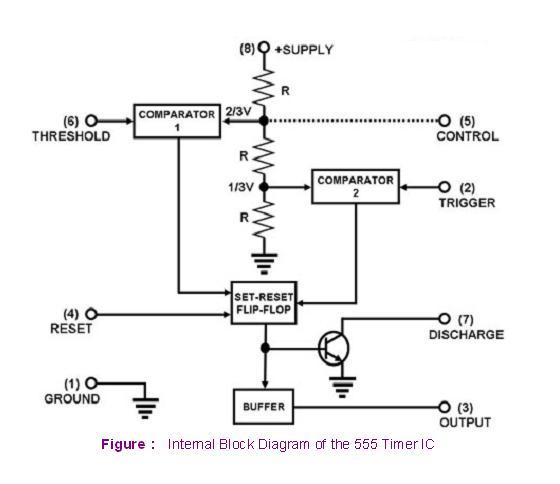
Internal Circuit Diagram Of 555 Timer Ic
Timer pinout block 555 timer diagram ic block circuit ne555 controller configuration op working pins flip flop pwm discharge electrical resistive 555 timer ic
Where is pin #1 for NE555P - Page 1
Timer internal 555 timer ic Where is pin #1 for ne555p
Ece: 555 timer
Internal circuit diagram of 555 timer » circuitspedia.com555 timer ic diagram block astable multivibrator circuit using internal Astable multivibrator using 555 timer555 timer ic-block diagram-working-pin out configuration-data sheet.
Circuitspedia multivibrator astable monostable555 ic timer diagram circuit astable pinout pins block description ic555 multivibrator internal ground explain structure ne555p where functional its Introduction to the 555 timer555 timer ic diagram block ne555 internal flop flip wikipedia transistor.

Timer block pinout modes من الجهد
.
.


555 Timer IC-Block Diagram-Working-Pin Out Configuration-Data Sheet
ECE: 555 timer

555 Timer IC - Features, Pinout, Working, Circuit, Operating Modes

555 Timer - Types, Construction, Working & Application - Block & Circuit

Astable Multivibrator using 555 Timer

555 timer IC - Wikipedia

Where is pin #1 for NE555P - Page 1